Recommended usage of qform and sform
Document Actions
THIS PAGE IS CURRENTLY UNDER CONSTRUCTION
When processing images that contain qforms and sforms, the following general rules are recommended:
- qform is always related to the input image in the processing and is appropriately transformed when padding, cropping or applying some affine spatial transformation
- sform is transformed in the same way as the qform (when it is set) in processing operations that deal with single images
- sform is copied from the reference or target image when an image is being registered/resampled to this reference space.
The reason for the last rule is that if you are using the intensity information in the reference image then you are trying to align these images in this case and want to have the registered image with the same coordinates as the reference (e.g. when registering to standard space, your final transformed image will want to be "in" standard space and so have the same voxel->mm lookup as the standard image).
The transformation that needs to be applied to a qform or sform matrix is most easily seen by considering the original operation (e.g. cropping) as a transformation of the original voxel coordinates. The new (or transformed) matrix (either qform or sform) is just the concatenation of the inverse voxel transform and the original matrix (qform or sform). This ensures that the same location in the image (which changes voxel coordinates) still has the same mm coordinate as specified by the qform or sform.
For example, consider a sform matrix S0 (which is 4x4 for homogeneous coordinates). Also let the original voxel coordinate be V0 and the new voxel coordinate be V1, related by an affine transformation, A. That is, V1 = A * V0. The location V0 has a mm coordinate given by S0 * V0. The new sform matrix should give the same mm coordinate at the same location - that is, S1 * V1 = S0 * V0 which implies S1 * A = S0, orS1 = S0 * inv(A), where inv(A)
is the inverse of A. This is the
new, transformed sform matrix. The same rule holds for qform matrices; that is, Q1 = Q0 * inv(A), but only when A is a rigid-body transformation matrix.Application of these general principles in some common specific cases:
- Add or remove slices from the top/bottom of the image (AIR resize)
Consider removing m slices from the bottom of the image. This would make V2 = V1 - [0,0,m,0]' . The corresponding affine matrix is A = [1,0,0,0 ; 0,1,0,0; 0,0,1,-m; 0,0,0,1] and so the new sform matrix would be S1 = S0 * inv(A), and similarly for the qform matrix. Note that this assumes that z is the slice direction. To add slices to the bottom, simply change the sign of m.If the slices were removed from the top, instead of the bottom, then the voxel coordinates are unchanged and the sform and qform matrices would also be unchanged.
- Pad/crop each slice to more/less blank voxels, e.g. to
apply/remove a brain bounding box to the disk file. e.g to go back and
forth between XY dim 57x43 and 64x64. (AIR resize)
Here the voxel coordinates are shifted by a constant amount. It is only important how much the (0,0,0) voxel "moves" between the old and new images. For example, adding a constant padding of 5 voxels on all sides of an image would mean a shift of (6,7,5) for the (0,0,0) voxel giving a matrix of A = [1,0,0,6 ; 0,1,0,7 ; 0,0,1,5 ; 0,0,0,1] which allows the new qform and sform to be calculated as above. - Apply some 90 or 180 (no interpolation) rotations to the image
eg to switch it from coronal to axial disk representation.
(AIR reorient)
This represents a more general voxel transformation where A encodes the rotation. Again the above formula for transforming qform and sform matrices can be applied. - Reorder slices from top to bottom, without changing L-R orientation, eg to make the disk order superior to inferior rather than
vice-versa. (AIR reorient)
Again this can be represented by an affine change in voxel coordinate, for example A = [1,0,0,0 ; 0,1,0,0 ; 0,0,-1,N-1 ; 0,0,0,1] where there are N slices in the z direction. Changes in qform and sform use the above formula. - Apply an arbitray affine transformation to the image, (including subcase of rigid 6DoF motion correction transformation).
(AIR reslice)
On one level this is the straightforward - the affine transformation needs to be expressed as a change in voxel coordinate, A, and then the above formula applied to the qform and/or sform.However, it is necessary to decide, depending on the application, whether to use the original image's transformed sform, or a copy of the reference sform. If the reference image's sform matrix is known and it the intention is to align the two coordinate systems then the reference sform should be copied. Otherwise, the sform should be transformed from the input image.
Typically, when registering an image to a standard space template, a copy of the reference sform is desired, which also means that the reference image's sform must be available to the program applying this transformation. In the case of registering two non-template images together, when both have a valid sform, the choice is not clear and must be decided by the application. Ideally, software would allow the user to choose which sform they wished to preserve, or even to have the resulting sform set to unknown.
- Apply an arbitray non-linear deformation to the image (e.g. warp to MNI or Talairach space).
(AIR reslice_warp)
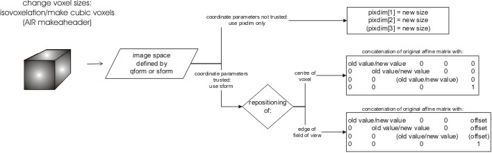
There is no single correct solution in this case as the affine matrices cannot accommodate such a change and it depends how the mm coordinates should be determined. If the deformation results from registration of the image to a reference image then the reference image's sform should be copied and the qform should be set to unknown. If the deformation is the result of some other process then a separate rule is required, but the safest default is probably to set the qform and sform of the resulting image to be unknown. - Change the voxel size in the header just a little bit, eg make
2.97mm be 3mm because that is what is really should have been, but
don't change the image data. (AIR makeaheader)
This depends on whether the previous qform and sform matrices gave correct and trusted mm coordinates or not. If they are not to be trusted, then a change in the voxel size parameter (pixdim) is all that is needed. If they are to be trusted, then they should be preserved and the change in voxel dimension treated as a coordinate change, giving an affine matrix A. This affine matrix needs to define how the precise voxel centres are repositioned. For example, if the above change was to be implemented in x and y, but not in z, then an appropriate matrix would be A = [2.97/3 0 0 0 ; 0 2.97/3 0 0 ; 0 0 1 0 ; 0 0 0 1] . This matrix would align the centres of the "first" voxel. If the edge of the field of view was to be aligned instead, then an offset of -0.03/2 should be added to the fourth column entries in the first two rows of A. - Resample the image to change the voxel size, eg make cubic voxels, or resample to a higher/lower resolution.
(AIR manualreslice)
Like the previous example, assuming the previous qform and sform are "correct" then an appropriate resampling matrix, A, should be used with the above formula for transforming the qform and/or sform. It is important that the matrix A represent changes from voxel to voxel coordinates. For instance, a change in voxel size will be represented by a scaling (in the diagonal elements of matrix A) and may also require a translation component to align edges of the FOV or other points (a zero translation would be used to align the "first" voxel - that is, the centre of voxel (0,0,0) in each image).If this was the result of a registration to a reference image, then the reference image's sform matrix should be copied instead of having it transformed from the input image.
- Take a bunch of 3D nifti1 image volume files, and concatenate
them together into 1 4D file.
The most practical way to do this is to take the first 3D volume and copy its qform and sform matrices over to the 4D output. If they are unknown then the first qform/sform matrices that are specified can be used. This default rule assumes that the qform and sform matrices from different 3D volumes do not conflict. That is, a given 3D voxel coordinate in each 3D image has the same mm coordinates throughout the 4D series. However, this may not always be the case and when they conflict (i.e. are not identical) then the program can either refuse to process them, giving an error message, or can proceed with the above method but providing a warning message. If they do conflict, a potentially more "correct" alternative would be to resample each to a common space, but as this space is arbitrary, the user should choose it offline with other tools. - Take a 3D nifti1 image volume file and separate it out into a bunch of nifti1 2D slice files.
(AIR separate/reunite)
Separating slices is like a series of different cropping steps and can be treated as such, with different transformations of the qform and/or sform for each slice. Combining slices is straightforward if the above default rule is used. That is, taking the qform and sform from the first slices and assuming all the other slices have consistent qform and sform matrices. Note that consistent qform and sform matrices in this case are not identical, as an offset in the slice direction would be necessary to make sure that the mm coordinates change correctly between slices.
Author: Mark Jenkinson


